Grid Assembly Tips
STEP 1: Site Preparation
- Allow tiles & edges to warm up with sunlight. Cold tiles & edges are stiffer and harder to connect.
- Anchoring tiles is only required if turning your front tires (while on tiles) cannot be avoided to enter or exit the Grid. We recommend 3/16” x 1.25” concrete anchor screws.
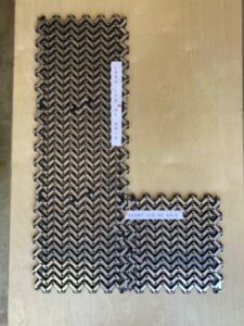
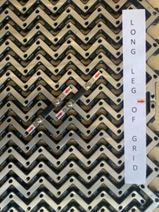
STEP 2: Laying out the tiles with proper Alignment.
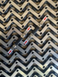
- Tiles now have X’s and O’s to help with correct Tile Bridge Installation.
- On either axis of the Grid (length or width) simply align the Tile side with O’s to the O’s on the connecting Tile and the X’s to theX’s.
- You may need to use a flat screwdriver to ensure that the metal edges where tiles contact are bent down such that they contact.
- Using a soft rubber mallet to gently tap tiles together is also a good way to go.
Refer to the photos at the right ->
STEP 3: Attaching the Bridge Connectors
- Each tile should have (2) bridge connections to the adjacent tile. On every tile there is an X and an O, this is to indicate where the bridges should be connected. X connects to X and O connects to O.
- To screw in the phillips screws to fasten the bridges use a power drill in a gentle power setting or screw in the bridge clips manually. Tighten the screws until snug.
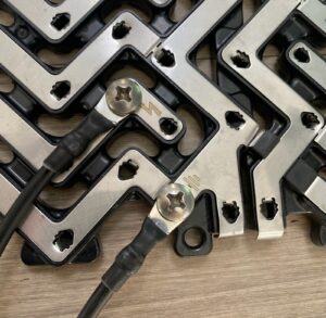
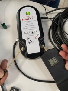
STEP 4: Connecting the Energizer
- Locate the Tile that is closest to your 110 volt outlet power source.
- At two corners of each Tile, you will notice Power Connection Symbols. Lightning Bolt and Ground Symbols, connect one end of each power cable to these Symbols and the other ends to the Energizer. Your energizer will indicate that it is functioning with either a red or green light.
- We recommend mounting your energizer off the ground and in an area where it will not be exposed to the elements.
STEP 5: Power on and voltage test the Grid.
Apply power to the energizer.
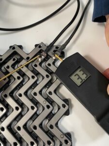
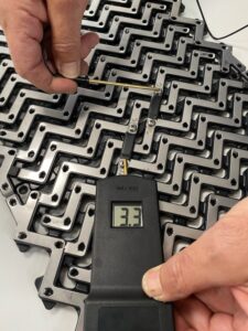
Using the supplied tester,
A: check the energizer before connecting the power wires. The voltage should be approximately 3KV, which will light up the lower 3 bulbs of the analog tester (500,1K,2K). If you have the new digital tester you will see a digital readout.
B: Next probe the power connection tile to ensure power is flowing from the energizer to the Grid.
C: Probe the tile furthest away from the power tile, usually it will be diagonal at the other end of the Grid. You should see a similiar voltage.
*** Congratulations, you have successfully installed GridGuard!
Please review the link below.